


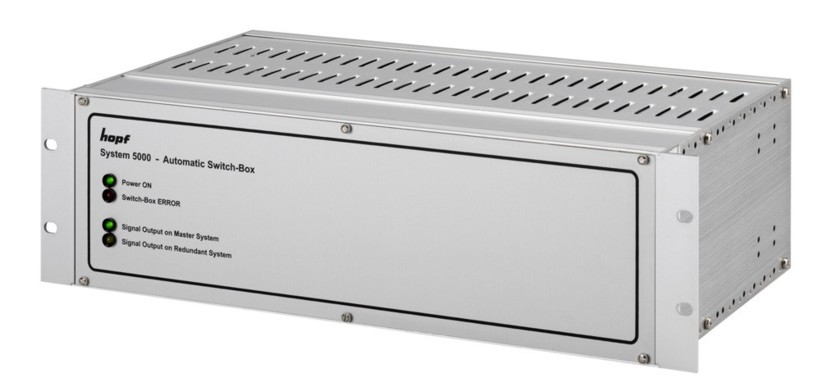
Switch-Box Base System 5000
Short Description
Switch-Box - System 5000 was designed and developed for setting up redundant clock systems in the 'hot standby function with automatic status-dependent signal switchover' operating mode.
Switch-Box - System 5000 is used when the most stringent demands are placed on the availability of a clock system.
The Switch-Box ensures that the signal output to the customer application is carried out at a low error level via the Clock System.
The Switch-Box realizes this fault-dependent signal switchover between the master and its redundant system by monitoring the status of the respective clock system. The Switch-Box can be configured in two different operating modes for this purpose:
-
Dynamic Error Status (for System 7001 and 7001RC)
In order to output the status information to the Switch-Box, clock systems 7001 and 7001RC generate special status information which can be picked up via a SUB-D connector on the front panel of Control Board 7020/7020RC.
Different priorities can be assigned to the various error messages in the clock systems in order to define optimum switchover conditions for the customer's application.
The clock systems can be monitored for 4 conditions in this mode:
- Total failure / line breakage
- Major fault
- Minor fault
- System O.K.
-
Static Error Status (for Series 6000 systems)
This mode was designed for Series 6000 clock systems; however in this mode the Switch-Box can also be controlled by external systems (on providing the required signals at a suitable signal level).
Two static signals of the clock systems are monitored in this mode:
- Operation/voltage O.K.
- Synchronicity O.K.
Due to the system's modular construction, the Switch-Box can easily be adjusted to the respective customer requirements or upgraded by the customer at a later date.
Thus specially adapted Switch-Boards, which generally facilitate easy connection between Switch-Box and clock system, are available for the various clock system output boards.
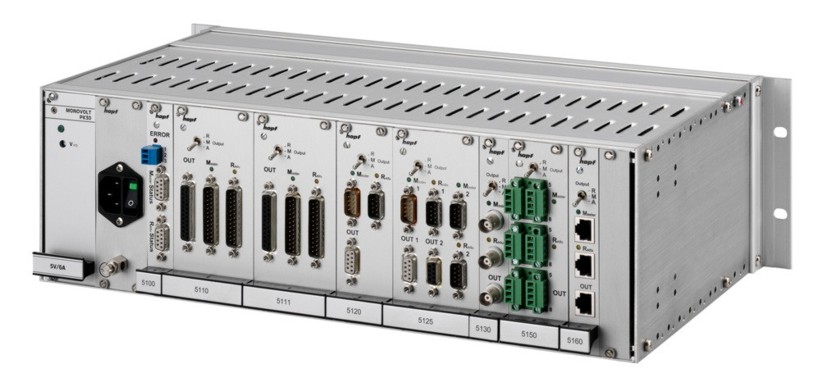
The basic system comprises:
- 1/1 19" rack 3U/84HP
- Standard power supply unit with 115/230V AC / 30VA (47-63Hz)
- Other input voltages and power supply units available
- Incoming voltage feed with mains switch and line filter
- Connection for protection earth cables up to 16mm²
- System front panel with status LEDs
Features
- Base system in 1/1 19" rack (3U/84HP) including Control Board 5100 and power supply unit
- Power supply 115/230V AC - other voltages possible
- Intelligent signal switchover dependent on the operating conditions of the Master and Redundant systems
- Free assignment of error priority in the hopf System 7001 and 7001RC
- Error and status reporting incorporated into Switch-Box for switchover availability over relay (dry contact) and LEDs
- All Switch-Boards are hot-plug compatible
- System completely maintenance-free
- All cable connections on the rear
- Status LEDs on both front and rear
- Casing with additional ground screw for cables up to 16mm²
- Incoming voltage feed with mains switch in accordance with IEC/EN 60320-1/C14 and EMI line interference suppression filter
- Prepared for customer retrofitting of Switch-Boards
- No additional blanking panels required on system expansion
- Casing extension with additional Switch-Board slots possible for larger systems
- Switchover mode for each Switch-Board adjustable via switch on the board faceplate (output fixed to Redundant System / output fixed to Master System / output controlled by Switch-Box)
- Complete electrical isolation of the Master and Redundant clock system output signals
- Easy expansion of existing stand-alone systems to a redundant system with 'hot standby function with automatic status-dependent signal switchover to redundant system'
- Parameterizable Switchover function: Switchover only by major error or Switchover by major and / or minor error
Expansion Options
- Customer-specific system adaptations for 'tailor-made' project solutions
Safety Concept
In the design of Switch-Box - System 5000 special emphasis was placed on the high availability of the complete clock system even during the presence of a fault.
The following aspects were taken into consideration for the different fault conditions:
- Signal output even in the case of Switch-Box voltage failure by means of signal switchover via relay (signal output always from the Master System in this case)
- Error message from the Switch-Box via relay and LEDs in the event of faulty transmission of status signals to the Switch-Box (e.g. broken cable)
- Error message from the Switch-Box via relay and LEDs followed by switchover or further output of the Master System's signals in the event of the transmission of ambiguous status signals to the Switch-Box
- Error message of the Switch-Box via relay and LEDs in the event of the total failure of the Master or Redundant System
- Error message of the Switch-Box in the event of power supply failure
- Error message of the Switch-Box via relay in the event of failure of Control Board 5100
- Manual configuration of signal outputs to the Master or Redundant System is possible (not in the event of power failure)
- In case of doubt the Master System's signals are always transmitted
Extensions
Switch Boards
Pictures
Downloads
PDF documents
Software and Driver
- For this product there is no Software / Driver available.