


Power Splitter 4449
Short Description
If only one GPS antenna for operating several GPS receivers can be installed (due to structural or other reasons), it is however possible to operate up to 8 GPS receivers with one common GPS antenna by using the active GPS antenna splitter 4449. This solution is often used in the context of superstructures for conducting device tests in laboratories or testing stations.
The active GPS antenna splitter 4449 contains 8 outputs and a signal amplification.
The GPS power splitter 4449 is available in two versions:
FG4449G00
Active GPS power splitter für GPS L1 antenna signal with 8 outputs and signal amplification. System-internal power supply via GPS antenna cable
The necessary voltage for operating the unit is supplied system-internally via the GPS antenna cable of the connected hopf GPS receivers plugged in the master output. No external power supply is needed to operate the unit.
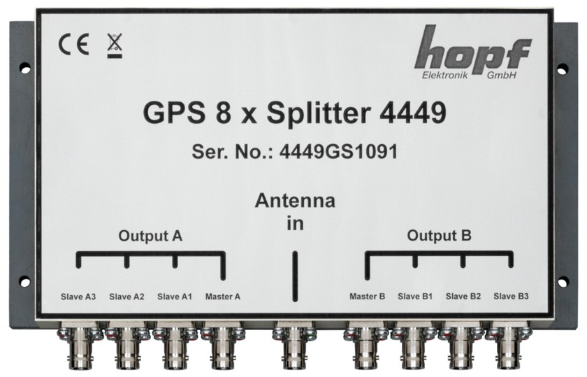
The application's 8 signal outputs are subdivided in 2 output groups (output A and output B) with 4 outputs each. Each output group has one master output and three slave outputs.
The supply voltage for the two output groups is respectively fed by the hopf GPS receiver which is connected to the master output of the output group. Without system-internally supplied voltage via the master output of an output group no signal output via this group takes place.
FG4449G01
Active GPS power splitter for GPS L1 antenna signal with 8 outputs and signal amplification. Power supply via external voltage source
An external voltage source (18-60V DC, Imax = 300mA) for feeding the antenna splitter is necessary. Connection of the 8 outputs to the application can be done in any sequence.
A system-internal power supply via the connected hopf GPS receivers is not necessary.
The active GPS antenna splitter 4449 is optionally available with a modification for connecting GPS receivers with antenna circuit monitoring. Due to this modification a current of approximately 13 mA per each output is achieved for connection of the hopf GPS receivers.
Technical Data
| General | |
|---|---|
| housing dimensions (high frequency housing incl. mounting plate and connections): | 149 x 242 x 30 mm (D x W x H) |
| power supply: | |
| FG4449G00 (system-internally via connected hopf GPS receivers): | 4.5 - 7V DC |
| FG4449G01 (external power supply): | 18 - 60V DC, Imax = 300mA |
| humidity: | 95% non-condensing |
| protection class: | IP50 |
| category of usage: | indoor, protected |
| MTBF value: | > 2,500,000 hours |
| weight: | approx. 1.2 kg |
| Electrical characteristics | |
| impedance: | input / outputs 50 Ω |
| frequency range: | GPS L1, 1575 MHz |
| band width: | ± 50 MHz |
| insertion loss per branch: | approx. 1 dB |
Pictures
Downloads
PDF documents
- Technical Manual GPS Antenna Equipment
- Data Sheet active GPS 8x Power Splitter 4449G00
(system-internal power supply via GPS antenna cable) - Data Sheet active GPS 8x Power Splitter 4449G01
(power supply via external voltage source)
Software and Driver
- For this product there is no Software / Driver available.